- English
-
EnglishDeutschItaliaFrançais한국의русскийSvenskaNederlandespañolPortuguêspolskiSuomiGaeilgeSlovenskáSlovenijaČeštinaMelayuMagyarországHrvatskaDanskromânescIndonesiaΕλλάδαБългарски езикGalegolietuviųMaoriRepublika e ShqipërisëالعربيةአማርኛAzərbaycanEesti VabariikEuskeraБеларусьLëtzebuergeschAyitiAfrikaansBosnaíslenskaCambodiaမြန်မာМонголулсМакедонскиmalaɡasʲພາສາລາວKurdîსაქართველოIsiXhosaفارسیisiZuluPilipinoසිංහලTürk diliTiếng ViệtहिंदीТоҷикӣاردوภาษาไทยO'zbekKongeriketবাংলা ভাষারChicheŵaSamoa日本語SesothoCрпскиKiswahiliУкраїнаनेपालीעִבְרִיתپښتوКыргыз тилиҚазақшаCatalàCorsaLatviešuHausaગુજરાતીಕನ್ನಡkannaḍaमराठी
E-mail:Info@YIC-Electronics.com
Comprehensive Guide to SCR (Silicon Controlled Rectifier)
Silicon Controlled Rectifiers (SCR), or thyristors, play a pivotal role in power electronics technology because of their performance and reliability. This article examines the structure, operation, and uses of thyristors in depth, highlighting the precise ways these devices manage and control high voltages and currents. We also look at the diverse types of thyristors and their packaging options, ensuring thyristors meet the requirements of various applications.
Thyristors are built from four alternating layers of P-type and N-type semiconductor materials. This design not only demonstrates advanced semiconductor physics but also adapts to multiple applications including power regulation, signal control, and energy conversion. The gate design of thyristors allows for meticulous control, enhancing the reliability and efficiency of power electronic systems. We discuss the gate control strategy of thyristors, focusing on how to enhance SCR performance and reliability by adjusting pulse amplitude, duration, and response to temperature changes. This part of the discussion delves into the technical specifics of optimizing thyristor operation under varying conditions.
Catalog

Figure 1: Silicon Controlled Rectifier
SCR Structural Design
The structural design of an SCR (Silicon Controlled Rectifier) primarily determines its functionality and electrical behavior, which is deeply rooted in semiconductor physics. SCR consists of a four-layer structure with alternating P-type and N-type semiconductor materials organized into a PNPN sequence.
Starting on the outside, the SCR has an outer layer of P-type material connected to the anode. This highly doped layer facilitates the forward mode of operation of the SCR because it accepts electrons from the cathode.
Next is a layer of lightly doped N-type material that sits beneath the outer P-type layer. This pair forms the first PN junction, called J1. When the SCR is forward biased, that is, the anode is positive relative to the cathode, J1 allows current to flow.
The third layer is another P-type material, but doped at a lower level than the outer layer, and is located between the two N-type layers. It forms the second PN junction J2. This layer prevents the SCR from conducting in the absence of a gate signal, even when forward-biased.
The innermost layer is directly connected to the cathode and is made of N-type material. It forms the third PN junction J3. When the SCR is reverse-biased, this layer blocks current flow, ensuring that the device conducts electricity in only one direction.
An SCR has three terminals: anode, cathode, and grid. The anode is the entry point for electrical current and is connected to the external P-type material. The cathode serves as the current outlet and is connected to the inner N-type material. This terminal helps release electrons to the anode when the SCR is turned on.
The gate is very important in controlling the SCR. Connected to the inner P-type layer, the gate is activated by applying a forward voltage, thereby changing the charge distribution in the middle P-type layer. The reduction in forward voltage at J2 allows the SCR to switch from a non-conducting state to a conducting state.
During operation, when forward-biased and the gate is active, J1 and J3 are forward-biased. The gate voltage affects J2 in the middle, which can handle the smaller forward voltage. This unique control setup of the SCR demonstrates its ability to change states, allow current to flow, and highlight the efficiency and precision of its power control.

Figure 2: The Structural Design of SCR
SCR Working Status
Silicon-controlled rectifier (SCR) operating response under various electrical conditions. This understanding facilitates optimal SCR application and management in power electronics.
In forward blocking mode, the SCR remains non-conductive even when a voltage is applied to make the anode positive relative to the cathode. This non-conducting state is due to the middle junction J2 being reverse biased, while the outer junctions J1 and J3 are forward biased. J2 introduces a high resistance barrier that prevents electrons from flowing from the cathode to the anode, effectively blocking the flow of electricity. This setup causes the SCR to act as a barrier to electrical current, appearing as a highly resistive element in the circuit.
In this state, two key parameters need to be observed: forward blocking voltage (V_BO) (the highest voltage the SCR can handle without conducting) and leakage current (I_L) (the smallest current that may still flow through the device ). Leakage current should be minimal to ensure the efficiency and safety of the SCR in blocking mode.

Figure 3: The Structural Design of SCR
The SCR switches to forward conduction mode when the voltage between the anode and cathode exceeds V_BO, or when sufficient gate pulses activate the device. In this mode, all three PN junctions J1, J2 and J3 become forward-biased. This change greatly reduces the internal resistance, allowing a strong current to flow from the anode to the cathode, similar to closing a switch.

Figure 4: Forward Conduction Mode
However, in order for the SCR to remain on, the current must not drop below the holding current (I_H). Falling below this threshold causes the SCR to return to its blocking state.
In reverse blocking mode, the anode is negatively charged relative to the cathode. This configuration reverse-biases the outer junctions J1 and J3, while the middle junction J2 remains forward-biased. Still, the SCR does not conduct due to the overall reverse bias from the external voltage. This setup effectively limits any substantial reverse leakage current, protecting the circuit from potential damage from high reverse voltages.
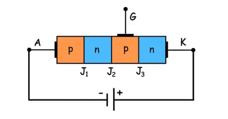
Figure 5: Reverse Blocking Mode
The main parameter here is the reverse blocking voltage (V_BR), which is the maximum reverse voltage that the SCR can withstand without the risk of avalanche breakdown. Circuit designs typically keep the operating reverse voltage well below V_BR to prevent damage and improve reliability.
SCR Control Technology
Efficiently control the operation of Silicon Controlled Rectifiers (SCRs) in a variety of applications involving power conditioning and switching. By fine-tuning the gate of an SCR, its performance can be controlled to meet specific electrical needs.
The role of the gate is the core of controlling the SCR to switch from a non-conducting state to a conducting state. It works by adjusting the internal charge distribution within the SCR's four-layer structure (PNPN). A controlled forward voltage pulse is applied to the gate, adding carriers (electrons and holes) to the interface between the Player and the adjacent N layer. The addition of carriers reduces the resistance at the central PN junction, making it easier for the SCR to transition from the blocking state to the active state at reduced voltages.
Pulse Properties: The intensity and duration of the gate pulse are important in activating the SCR. Stronger pulses can speed up the activation of the SCR, but risk increasing the gate current, possibly damaging the SCR. Therefore, balance pulse intensity and length for fast and safe activation.
Temperature Effect: Temperature changes can affect how the SCR triggers. The design of the gate drive circuit must take these variations into account to ensure that the SCR triggers reliably at any expected temperature.
dv/dt sensitivity: The SCR's response to changes in terminal voltage (dv/dt) is a subtle issue. High dv/dt rates may cause the SCR to trigger unexpectedly. To avoid this, the control circuit should regulate the rate of voltage change to prevent accidental activation.
In power management tasks, SCR gate control is usually aligned with the current requirements of the load. For example, in applications such as AC lighting dimming or motor speed regulation, the gate pulses are phase-synchronized with the AC power supply. This timing adjustment, called phase control, modifies the average current through the SCR, allowing for precise power adjustment.
For protection, the SCR plays a role in the overcurrent protection setting. The gate control circuit is calibrated using a specific current trigger threshold. If the current exceeds this threshold, the SCR activates, rerouting the current to prevent damage, or possibly triggering a circuit breaker to protect the primary circuit.
SCR Characteristics
Silicon-controlled rectifiers (SCRs) play a pivotal role in power electronics with six key properties that play a key role in their various industrial uses. These properties outline its functionality, durability, and range of applications.
SCRs allow current to flow in one direction: from the anode to the cathode. This feature positions the SCR as a switchable rectifier in a circuit, similar to a diode, but with enhanced control capabilities. An operator can start or stop the flow of current through the SCR by manipulating the gate (a small voltage or current pulse). This precise control sets SCRs apart from traditional diodes.
A small gate pulse is required to turn on the SCR. Interestingly, once activated, the SCR continues to conduct even when the gate pulse is stopped, and it only stops conducting when the current drops below a certain threshold (called the holding current). This feature is particularly valuable in applications that require a regulated power supply, allowing operators to maintain or interrupt power flow with high precision.

Figure 6: One-Way Conductive Device
SCRs are designed to manage large electrical loads and are capable of handling high voltages up to thousands of volts and currents up to thousands of amps. This powerful capability makes it ideal for demanding environments such as power transmission and heavy industrial motor control.
SCRs vary widely in their sensitivity to triggering stimuli, depending on their design and material composition. Some SCRs are very sensitive and can be activated with minimal gate current or voltage, which is advantageous in applications that require controlling high-power loads with low-power signals. This variability allows for customization to specific operational requirements.
SCRs exhibit reliable performance even in high-temperature environments, which benefits applications in challenging conditions such as industrial control systems and power infrastructure. Nonetheless, effective thermal management can ensure SCR durability and consistent performance and requires careful design considerations.
SCRs often outperform other power control options in terms of cost-effectiveness and operational reliability. Its simple design helps reduce maintenance costs and improves reliability, making SCRs an economically viable option for many systems requiring long-term operational stability.
These properties make SCR useful in a variety of applications. They play a key role not only in controlling motor speed and power regulation but also in rectifiers, inverters, and electronic switches.
Type of SCR
Silicon-controlled rectifiers (SCRs) are available in a variety of types and packages, each tailored to the specific needs of the power electronics world. From simple power regulation to complex power conversion, the diversity of SCR technology demonstrates its versatility.
Standard SCRs cover a wide range of general power control tasks. These SCRs are typically used in medium power applications such as motor starting and speed control, heater regulation, and various power conditioning devices and are designed to efficiently handle considerable current and voltage levels. Operators often choose standard SCRs because of their proven reliability in maintaining stable operations in a variety of industrial and commercial environments.
Fast-switching SCRs are designed for applications requiring fast response times and are ideally suited for use in frequency converters, pulse-modulated systems, and high-speed power supplies. Their activation and deactivation times are faster than standard SCRs, which increases system efficiency and reduces switching losses. These properties are particularly useful in high-frequency environments, where energy losses are minimized.
Reverse conducting SCRs integrate the reverse diode in the same unit, simplifying circuit layout and reducing component count in the AC power system and frequency converter. This integrated approach allows these SCRs to conduct current forward while blocking reverse current, thereby improving efficiency and reliability in applications such as controlled rectifiers and AC-DC converters.
Gate-triggered SCRs (or GTOs) differ from traditional SCRs in that they can be turned on and off with a gate signal. This dual functionality makes the GTO extremely valuable in scenarios requiring fast and repeated switching, such as high-power inverters, traction drives, and complex power management systems. GTO provides the control flexibility and precision required to meet the stringent requirements of these high-power applications.
By studying these different SCR types, we can understand how thyristor technology meets the evolving needs of power electronics, from basic functionality to advanced power management. Selecting the appropriate SCR type depends on the specific application needs and takes into account factors such as power requirements, switching dynamics, control flexibility, and overall system design. Each SCR variant brings unique advantages to the scenario in which it is used, emphasizing the importance of precise selection based on targeted application objectives.
SCR Packaging Types and Their Impact
The packaging of a silicon-controlled rectifier (SCR) is very important as it affects its thermal management, electrical performance, and suitability for various applications. Different packaging types are designed to optimize the SCR for specific conditions and requirements, thereby increasing its effectiveness and performance in different environments.
Discrete plastic packaged SCRs are primarily used in low to medium-power applications. This type of packaging is common in consumer electronics and general industrial machinery and is favored for its affordability and compact size. However, plastics do not conduct heat as efficiently as metals, so additional cooling measures, such as heat sinks or fans, are required to maintain safe operating temperatures. This packaging solution is ideal when cost concerns outweigh extreme thermal performance requirements.

Figure 7: Discrete Plastic Packaging
Plastic module packages are designed to meet more demanding power requirements and can accommodate multiple SCRs or a combination of different semiconductors, including diodes and transistors. This approach is prevalent in high-power motor drives and controllers, providing enhanced thermal management and mechanical robustness. Plastic module packaging not only improves circuit reliability but also simplifies the assembly process, saves space, and reduces system design complexity.

Figure 8: Plastic Module Packaging
Stud base packages offer excellent thermal conductivity and are preferred for high-power applications. These packages have a metal base that directly contacts the heat sink, helping to dissipate heat efficiently. The design also allows for stable mechanical installation and easy integration with cooling systems, making it ideal for handling large amounts of current in high-load environments.

Figure 9: Stud Base Packaging
Similar to the stud base package, the flat base package is also suitable for high-power applications but offers different mounting and thermal interface options. These are typically bolted together to enhance the modular system design, ensuring effective thermal contact and mechanical stability. Because the flat-bottom package is easy to install and remove, it is particularly beneficial for systems that require regular maintenance or replacement of components.

Figure 10: Flat Base Packaging
Press-fit packages are designed for applications that handle extreme currents and voltages. Typically constructed from durable ceramic materials, this package type provides excellent durability and electrical isolation, making it suitable for harsh industrial environments and power infrastructure. Its mechanical strength and thermal stability ensure reliable operation under stringent conditions, especially in power transmission and distribution equipment.
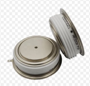
Figure 11: Press-Fit Packaging
Each SCR package type offers unique advantages tailored to specific application needs, reflecting the importance of selecting the right package to maximize SCR performance and reliability in the intended environment. Careful consideration of packaging ensures that SCRs can effectively meet the diverse needs of modern power electronics systems.
Conclusion
We explore the complexity of silicon-controlled rectifiers (SCRs), from their basic structural elements to their diverse operational roles in power electronics. SCRs stand out in the field due to their unique features such as unidirectional conduction, precise controllability, high current and voltage capacity, triggering sensitivity, thermal resilience, and overall reliability and cost-effectiveness.
By dissecting their operational status, we gain insights into how SCRs function as critical components in power systems, promoting efficient, safe, and stable power management. The refinement of gate control strategies demonstrates the need for fine adjustments that can tailor the SCR's performance to specific environmental and application needs, ensuring optimal functionality in different settings.
Continuing research and development in this area is not only pushing the limits of power electronics technology but also ensuring that these systems become increasingly more efficient, ensuring their status as an essential element of modern power infrastructure. This analysis reiterates the essence of SCR and highlights the importance of further innovation in thyristor technology.
Frequently Asked Questions [FAQ]
1. How to troubleshoot a silicon-controlled rectifier (SCR) circuit?
To start troubleshooting an SCR circuit, first, connect the negative (black) lead of your tester to the SCR's cathode. Next, attach the positive (red) lead to the anode (or stud). Normally, the tester should light up. However, when you momentarily connect the cathode and anode leads together, it should switch the SCR off. This reaction indicates a functioning SCR.
2. How do I choose an SCR?
When selecting an SCR, consider its performance specifications. Focus on the peak repetitive reverse voltage, which is the highest voltage that can continuously be applied to both the anode and cathode without causing damage.
3. How do I check if my SCR is faulty?
To check if an SCR is faulty, use a multimeter to measure the resistance between the anode and cathode and vice versa. In a non-faulty SCR, the resistance should read very high, typically in the megohms range. A low reading suggests a short SCR.
4. What causes SCR failure?
SCRs often fail due to power surges and spikes, which may occur in 3 3-phase power distribution circuits. These disturbances can lead to overvoltage conditions that overwhelm the SCR, causing it to short and fail.
5. How do I identify SCR terminals?
You can identify the terminals of an SCR using a continuity meter. The terminals that show any continuity between them are the gate and cathode. This method is reliable for pinpointing these specific terminals.
Related Blog
-
Fundamentals of Op-Amp Circuits
![Fundamentals of Op-Amp Circuits]()
December 28th, 2023
In the intricate world of electronics, a journey into its mysteries invariably leads us to a kaleidoscope of circuit components, both exquisite and co... -
How Many Zeros in a Million, Billion, Trillion?
![How Many Zeros in a Million, Billion, Trillion?]()
July 29th, 2024
Million represents 106, an easily graspable figure when compared to everyday items or annual salaries. Billion, equivalent to 109, starts to stretch t... -
Comprehensive Guide to SCR (Silicon Controlled Rectifier)
![Comprehensive Guide to SCR (Silicon Controlled Rectifier)]()
April 22th, 2024
Silicon Controlled Rectifiers (SCR), or thyristors, play a pivotal role in power electronics technology because of their performance and reliability. ... -
CR2032 lithium-ion battery: multi-scenario applications and its unique advantages
![CR2032 lithium-ion battery: multi-scenario applications and its unique advantages]()
January 25th, 2024
The CR2032 battery, a commonly used coin-shaped lithium-ion battery, is essential in many low-power electrical products such as digital watches and po... -
NPN and PNP Transistors
![NPN and PNP Transistors]()
December 28th, 2023
For exploring the world of modern electronic technology, understanding the basic principles and applications of transistors is essential. Although the... -
What is a thermistor
![What is a thermistor]()
December 28th, 2023
In the realm of modern electronic technology, delving into the nature and working mechanism of thermistors becomes a crucial endeavor. These precision... -
Explore the Difference Between PCB and PCBA
![Explore the Difference Between PCB and PCBA]()
April 16th, 2024
A PCB serves as the backbone of electronic devices. Made from a non-conductive material, it physically supports components while also connecting them ... -
BC547 Transistor Comprehensive Guide
![BC547 Transistor Comprehensive Guide]()
July 4th, 2024
The BC547 transistor is commonly used in a variety of electronic applications, ranging from basic signal amplifiers to complex oscillator circuits and... -
What Is A Solenoid Switch
![What Is A Solenoid Switch]()
December 26th, 2023
When an electrical current flows through the coil, the resulting magnetic field either attracts or repels the iron core, causing it to move and either... -
IRLZ44N MOSFET Datasheet, Circuit, Equivalent, Pinout
![IRLZ44N MOSFET Datasheet, Circuit, Equivalent, Pinout]()
August 28th, 2024
The IRLZ44N is a widely-used N-Channel Power MOSFET. Renowned for its excellent switching capabilities, it is highly suited for numerous applications,...


Hot Parts
- W39F010P-70Z
- SY10E112JC
- MSP430G2855IRHA40R
- ICP-N15
- CSC4863S
- RF1480TR7X
- ATSAM4LC2AA-AU
- AU5517DR2G
- AD7657YSTZ-1
- AD7225KRZ-REEL
- SSL126ETN-A2-0-TR
- MC68E030FE40C
- KSZ9021RLI
- C1608C0G1H3R9B
- EDK107M035A9HAA
- K9F2808UOB-D
- 12065C154JAT4P
- GRM1555C1H9R9WA01D
- DZ2S082M0L
- RTR025N03 TL
- AT29C010A-90TC
- SN8P1602BP018
- EPF10K10ATC144-3N
- D2W215CF
- 2SC3647T-TD-E
- K7A803600B-QC16
- MX29LV160DTTI-70G
- M29F400BB-90N6
- Z8523008VEG
- T495X226M035ATE300
- NLV27WZ17DFT2G
- MC9S08AW16CPUE
- LTC2238CUH#TRPBF
- C0805C101K3GACTU
- GRM155R61A154ME19J
- LM4816MTX/NOPB
- T491D337K006AT7027
- T491C156K010ZTAC00
- BZX384C5V6-V-GS08
- EMC2300AZC
- ET51530YB
- OXUFS936DSE-FBAG
- PCF8591T/2518
- STI5189ZBB
- TPA6013PWPR
- MBG044PBS-M-K2E1
- TEA6856HN/V102
- ZPSD312B-90JI

